Overview of Injection Molding Machine Parts
Injection molding machine parts are components used on the plastic injection molding machines.
The parts include Injection unit, clamping unit, hydraulic unit, and electrical unit.
Above four units make up the entire injection molding system and play an important role in the injection molding production process.
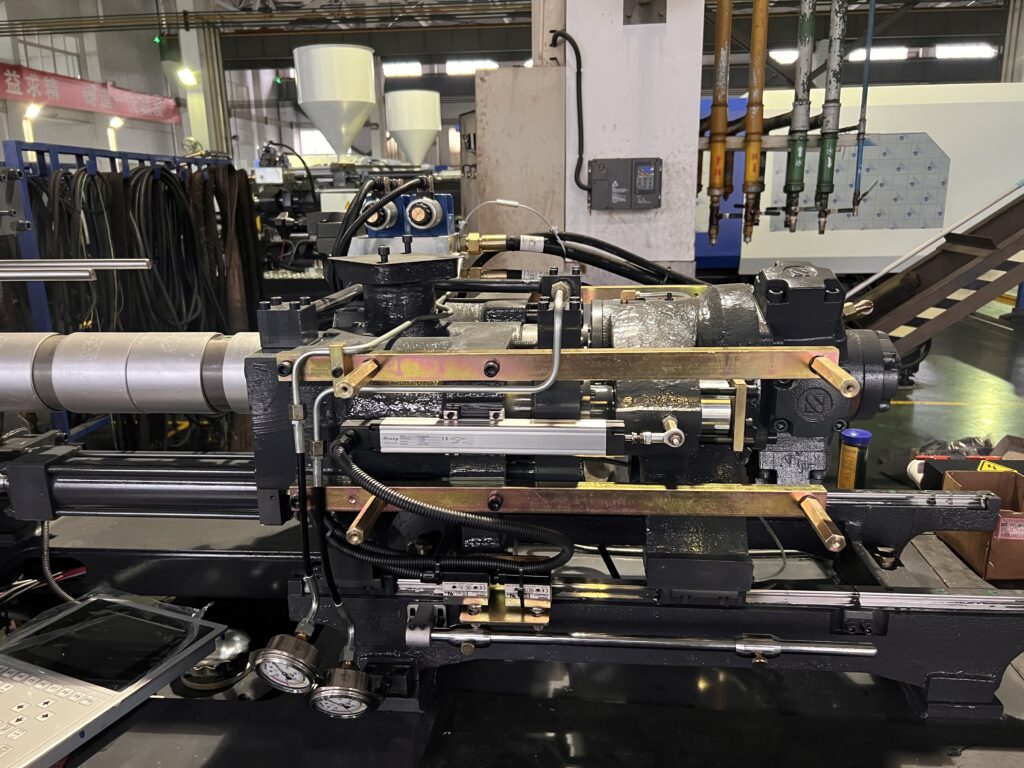
Injection Unit
Injection cylinder
The injection cylinder is supplied with oil, which causes the piston to move the piston rod and bearing in the thrust seat, resulting in the injection screw moving forward or backward.
The positions of the two parallel piston rods and the injection screw can be synchronized by adjusting the nut on the head of the piston rod.
Injection base shift cylinder
The transfer device connects to the injection base, which moves forwards or backwards when oil is introduced to the cylinder.
This movement ensures that the injection nozzle is in close proximity to the primary sprue of the mold, creating injection base pressure which seals the molten plastic.
Screw
The screw is a crucial component of the plasticizing process, as it directly interacts with the plastic.
Plastic flows through the screw’s grooves, undergoing a thermal transformation through three stages: glass state, viscoelastic state, and viscous flow state.
The functional sections, length, geometry, and geometric parameters of the screw all have a significant impact on the efficiency of plastic delivery and the quality of plasticization, which in turn affects the cycle time of the injection molding process and the quality of the final product.
Screw head
Injection molding machines screw heads have a role of releasing melted plastic into the storage chamber during pre-molding and preventing backflow during high-pressure injection.
Two main types of screw heads exists: with or without a stop collar.
Barrel
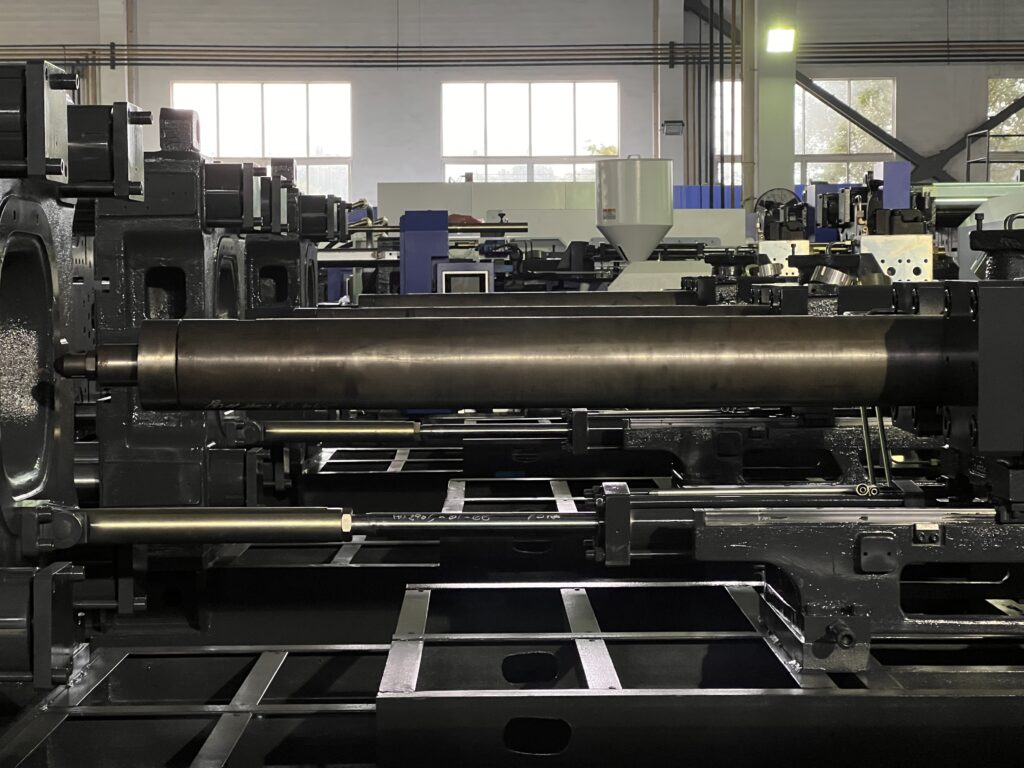
The barrel, which is an essential component of plasticizing equipment, houses a screw and is surrounded by heating bands.
It is subjected to both thermal and compressive stress.
To withstand these conditions, the barrel and screw are typically made of high-quality nitrided 38CrMoAlA steel, known for its high temperature wear and corrosion resistance.
For processing specific reinforced fiber-filled composite materials, the barrel may be upgraded to a bimetallic version, made of a high-carbon, high-chromium alloy, that offers increased hardness, corrosion resistance, and wear resistance.
Nozzles
The nozzle connects the plasticizing device to the mold runner and plays a crucial role in the molding process.
During the pre-molding phase, the nozzle creates back pressure at the head of the screw to prevent the melt from flowing out.
In the injection phase, the nozzle generates injection pressure, promotes energy conversion and homogenization of the melt temperature, and also maintain holding pressure, it also acts as insulation and shrinkage regulator.
Nozzles can be classified into different types such as open nozzle, locking nozzle, hot runner nozzle and multi-runner nozzle.
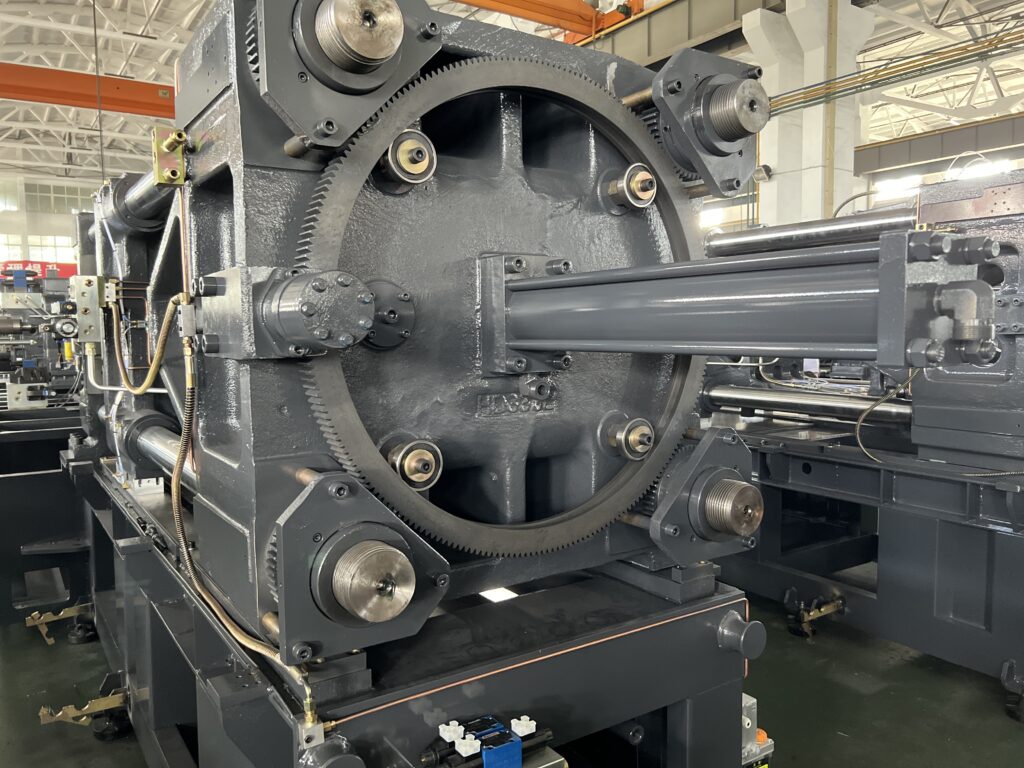
Clamping Unit
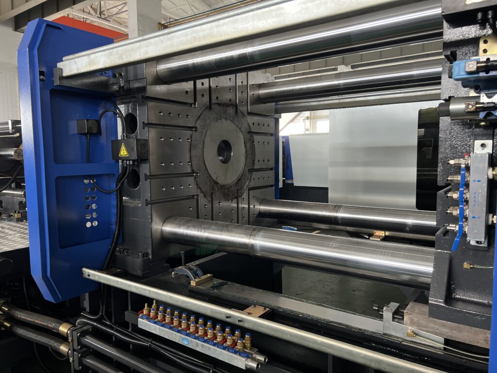
Platens
The front and rear platens, along with the tie bars, form the injection machine clamping mechanism.
When the mold is clamped, the moving and fixed platens lock the mold in place and subject it to compression and deformation under the clamping force.
As a result, all three platens will experience bending and deformation, with the middle template experiencing the most deflection.
The properties of the platens, such as its structure, size, material, and elastic modulus, have a direct impact on the strength, rigidity and clamping force of the mold closing system.
The templates are usually made of ductile iron or cast steel.
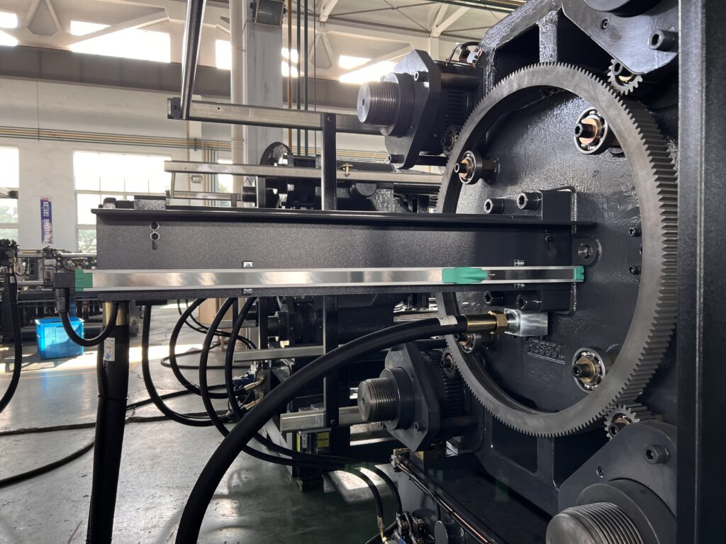
Tie Bar
The tie bar is one of main components of the mold clamping system, it helps form a rigid frame together with the platens, and also acts as a guide pillar.
The moving platen slides along the tie bar, therefore, high precision, smooth finish, and good wear resistance are required.
The thread on the tail end of the tie bar and the mold adjusting nut work together to adjust the clamping force.
Tie bars are commonly made of materials such as 38CrMoAlA, 40Cr and 45 steel.
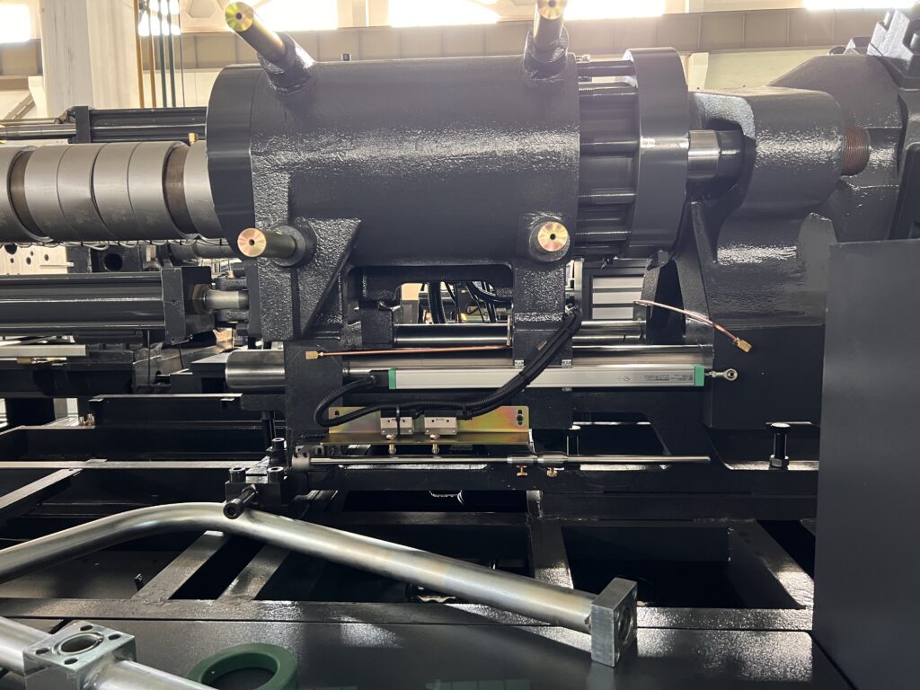
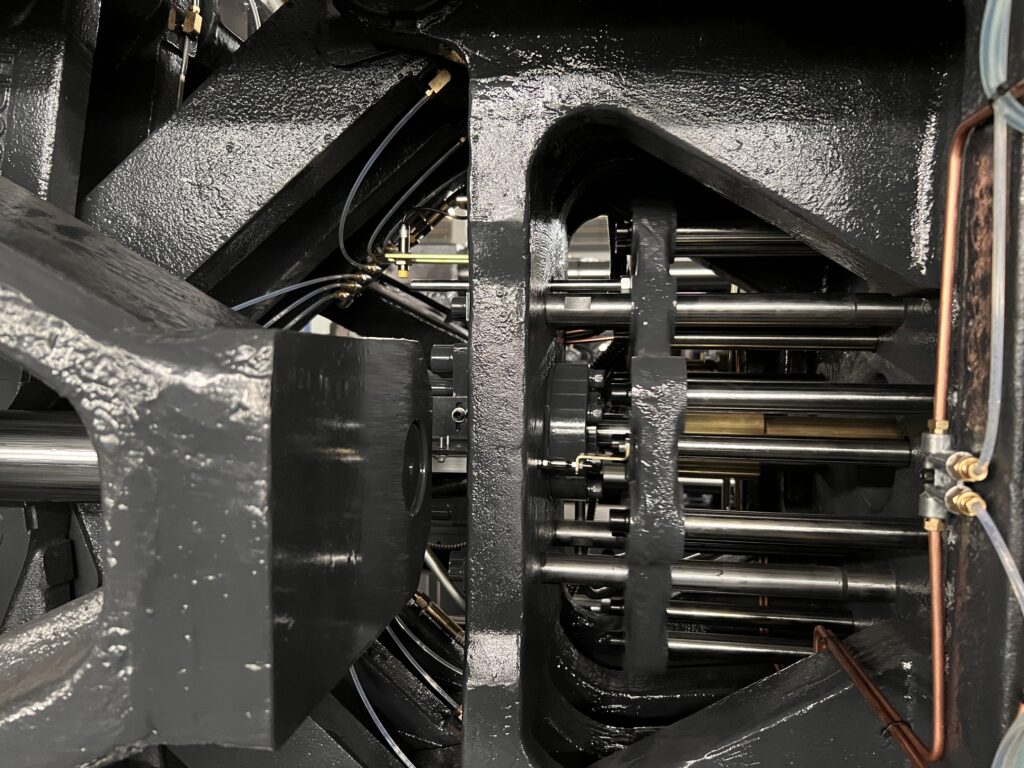
Bending elbow linkage
The rear linkage connects the tail plate’s support hinge with the front linkage and the hinge support on the second plate, using a large pin and steel sleeve.
The small connecting rod is attached to the rear connecting rod with a small pin and steel sleeve, and the other end connects to the hinge support on the thrust seat.
The clamping cylinder piston rod, which is fixed to the tail plate, is adjusted with the clamping rod tightening nut and secured to the thrust seat.
The thrust seat has a horizontal locking hole with a guide sleeve, which guides the sliding of the piston rod to the clamping platen tie bar.
The thrust seat is driven by the small linkage to drive the crank elbow and the front linkage, moving the platen and enabling the opening and closing motion of the mold.
Mould adjustment device
The rear linkage connects the tail plate’s support hinge with the front linkage and the hinge support on the second plate, using a large pin and steel sleeve.
The small connecting rod is attached to the rear connecting rod with a small pin and steel sleeve, and the other end connects to the hinge support on the thrust seat.
The clamping cylinder piston rod, which is fixed to the tail plate, is adjusted with the clamping rod tightening nut and secured to the thrust seat.
The thrust seat has a horizontal locking hole with a guide sleeve, which guides the sliding of the piston rod to the clamping plate tie bar.
The thrust seat is driven by the small linkage to drive the crank elbow and the front linkage, moving the dynamic platen and enabling the opening and closing motion of the mold.
Ejector parts
The primary components of an ejector device include an ejector cylinder which is fixed to the supporting hinge on the moving platen, as well as an ejector rod.
Additionally, the device requires sufficient force, speed, repeatability, and accuracy for proper ejection.
The ejector cylinder generates the power for ejection, while the ejector rod typically includes a primary component and multiple secondary ejector rods.
Mechanical safety device
To guarantee the safety of personnel, machinery, and molds, a mechanical safety device is implemented to prevent accidental operation.
This device is activated in case of failure in the safety program or electric and hydraulic systems, preventing the moving platen from closing the mold if the safety door is not closed.
This is accomplished through the use of a bending elbow linkage mechanism, which limits the movement of the moving platen when it is not properly closed.
In this state, the angle of the bending elbow (α) is near its maximum, resulting in a minimal force amplification ratio, and thus a minimal thrust from the moving platen.
The mechanical brake on the moving platen serves as an additional safeguard to ensure safety.
Clamping cylinders
The clamping cylinder, also known as the clamping cylinder, is attached to the fixed platen.
It uses the pressure of the hydraulic oil in the cylinder to move the piston inside the cylinder back and forth.
The movement of the piston, in turn, causes the platen to move through the piston rod.
As the mold is fixed to the platens, this action opens and closes the mould, completing the injection molding process.
Hydraulic Unit
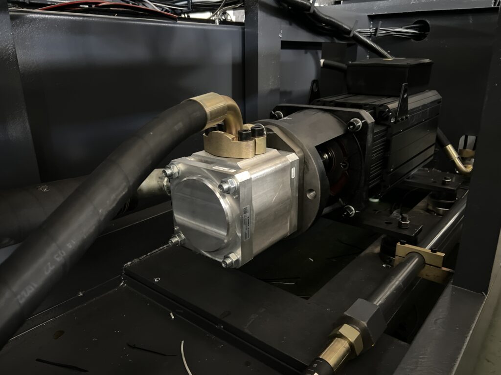
Hydraulic pump
The oil pump functions by reducing the volume of the cavity.
When an external force causes the crank to rotate, the piston moves in a linear, back-and-forth motion.
As the piston moves to the right, the cavity expands, creating a vacuum.
Under the pressure of the surrounding atmosphere, oil is drawn from the tank through a one-way valve into the cavity, closing one-way valve B.
When the piston moves to the left, the cavity volume decreases, closing one-way valve A, and oil is forced into the system through the other one-way valve.
There are several types of pumps that are commonly used, including gear pumps, vane pumps, piston pumps, and servo-controlled variable pumps.
Hydraulic valves
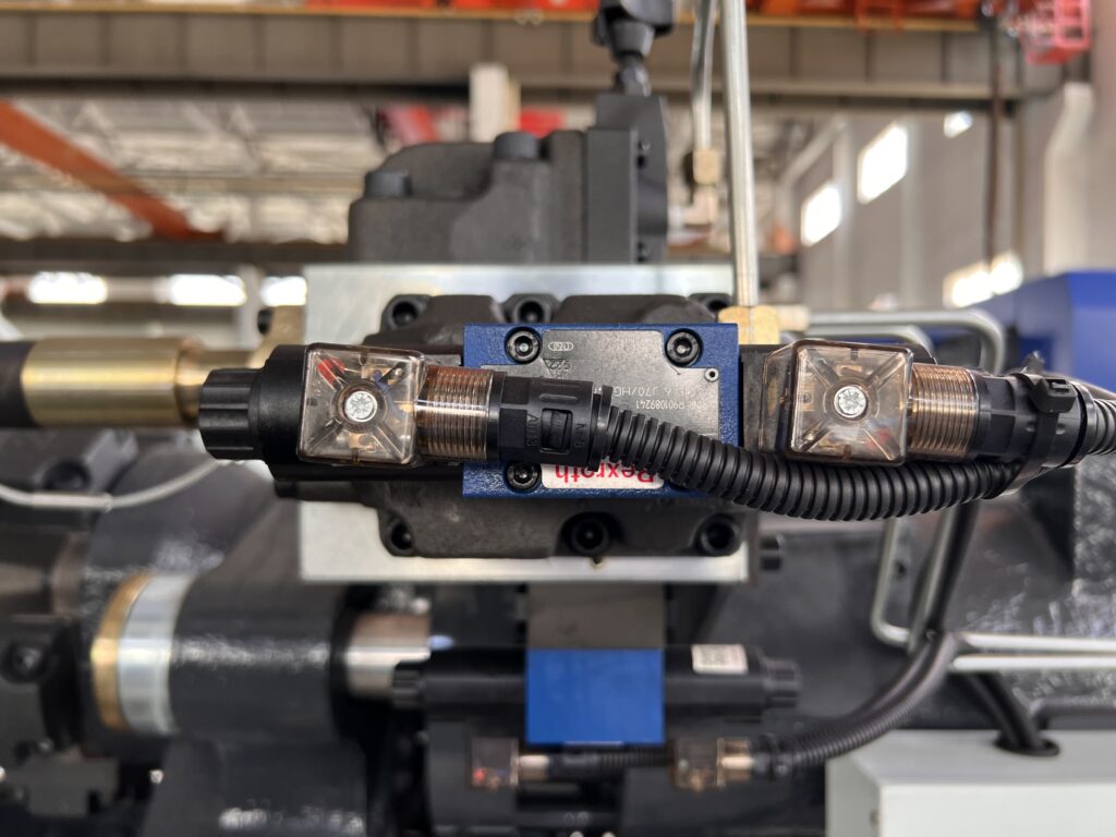
Hydraulic valves serve the function of controlling and regulating the pressure, flow and direction of the oil in the system.
A relief valve is a safety device that is used to limit the system pressure and protect the system components, as well as prevent damage to the pipeline due to excessive pressure.
Pressure reducing valves utilizes the principle of liquid resistance to reduce the pressure of the oil at the outlet, making it lower than at the inlet.
A one-way valve allows oil to pass through in only one direction and prevent it from flowing in the opposite direction.
A solenoid reversing valve uses a solenoid signal to control the movement of the valve and change the direction of the oil flow in the system.
A proportional valve is a control valve that regulates the flow, pressure, and direction of oil in proportion to the input electrical signal.
A servo valve is a control valve that can continuously adjust the flow and direction of oil and combined with a feedback device to provide precise control of the actuator’s position and speed.
Hydraulic cylinders
The cylinder in a hydraulic system converts energy from pressurized fluid into mechanical movement.
The double-acting piston rod type cylinder is the most commonly used in the injection molding machine.
By applying pressure to the back cover, oil flows into the cylinder and when the pressure is sufficient enough to overcome the forces acting on the piston rod, the piston moves uniformly in both directions and the piston rod provides mechanical energy to the outside world.
The efficiency of a hydraulic cylinder is composed of two factors: volumetric efficiency and mechanical efficiency.
Volumetric efficiency is affected by the presence of internal or external leakage in the cylinder.
Mechanical efficiency is based on factors such as the type of oil seal, condition of the piston rod, the inner surface roughness of the cylinder barrel, and the pressure of the system.
Hydraulic motor
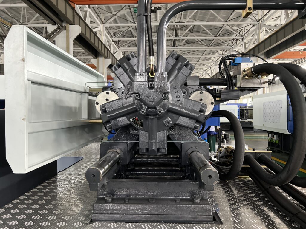
A hydraulic motor is a mechanism that converts hydraulic energy into rotational torque and speed on the output shaft.
The amount of torque produced by the shaft is determined by the pressure of the oil, while the speed of the shaft is controlled by the flow rate of the oil input.
There are several different types of hydraulic motor, including gear, vane, and plunger designs.
Hydrauic pipes and fittings
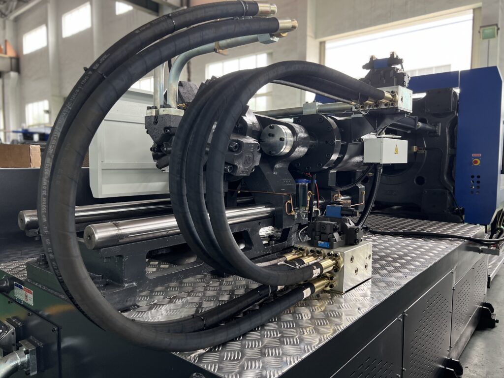
In order to form a complete hydraulic system, the hydraulic components, auxiliary parts, and measuring instruments are connected together using appropriate fittings, such as pipes and joints.
These fittings should be strong enough to withstand the pressures of the system, reliable, easy to install and disassemble, and have minimal energy loss when transporting the working media.
On injection molding machines, the pipes used are a combination of hard pipes and hoses.
Hard pipes can be further classified into steel and copper pipes.
While hoses are divided into plastic and metal hoses.
Oil filter
An oil filter is a device that removes impurities from oil.
It does this by using a filter element that catches and holds small particles, such as dirt and debris, so they can’t flow through to the rest of the engine.
The filter’s efficiency is a measure of how well it is able to capture these particles.
It’s determined by comparing the number of particles that pass through the filter to the number of particles that were in the oil before it was filtered.
Hydraulic oil cooler
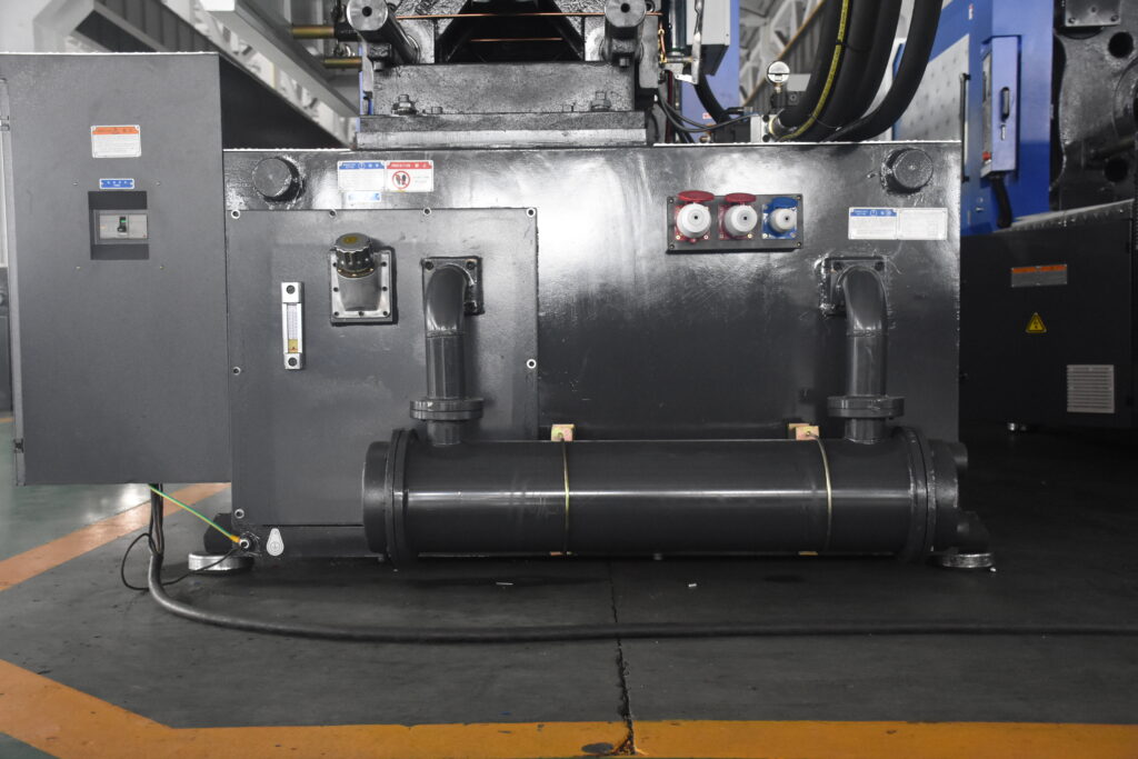
Hydraulic oil coolers are devices that cool down hot oil by using water.
They work by running the hot oil and cool water through separate parts of the cooler, which are connected so they can exchange heat.
Water-cooled coolers use fresh water as the cooling agent.
The oil flows through one part of the cooler and the water flows through another, and they transfer heat between each other, which causes the oil to cool down.
When the cooler is not in use for a long period of time, the fluids inside should be emptied to prevent it from freezing.
Hydraulic oil
Hydraulic oil is the working medium of hydraulic transmission system.
When the ambient temperature is high, high viscosity oil should be used; conversely, low viscosity oil should be used.
For example, in winter, use #10-20 hydraulic oil; in summer, use #20-30 hydraulic oil.
System working pressure is high, use high viscosity hydraulic oil.
Because of high pressure, sealing is difficult and easy to leak.
On the contrary, it is appropriate to use hydraulic oil with small viscosity.
When the system working parts speed is high, the fluid flow rate is high, the pressure loss is large, the leakage is reduced, it is appropriate to use low-viscosity oil.
On the contrary, high viscosity oil is recommended.
Electrical Unit
Stroke switch
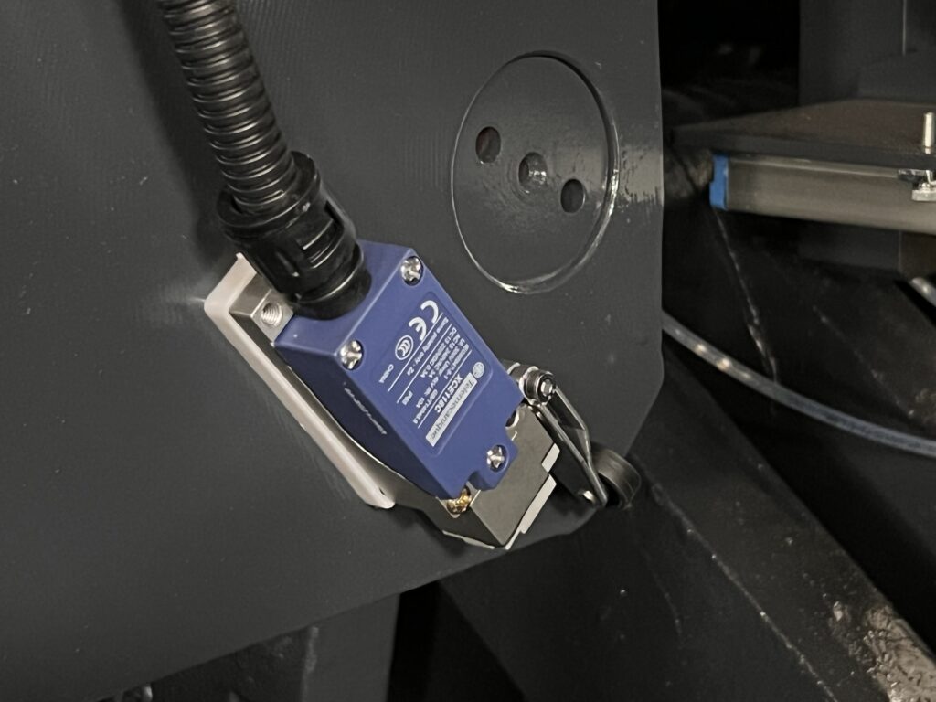
A travel switch, also known as a limit switch, is a device that sends control signals by using mechanical movement.
They are mainly used to control the direction of movement or to protect the position of equipment.
They work by sensing the position of moving parts, such as safety gates, and sending a signal to the control unit to protect the machinery.
Proximity switch
Proximity switches, are commonly used in industrial production for a variety of purposes, such as travel control, limit protection, high-frequency counting, liquid level control, detection of part size, and automatic connection of processing procedures.
They have several advantages over traditional contact travel switches, such as stability, reliability, long life, repeatable positioning, high accuracy, and the ability to withstand harsh working conditions.
In the circuit of an injection molding machine, both proximity and travel switches can be used for similar purposes.
Displacement sensors
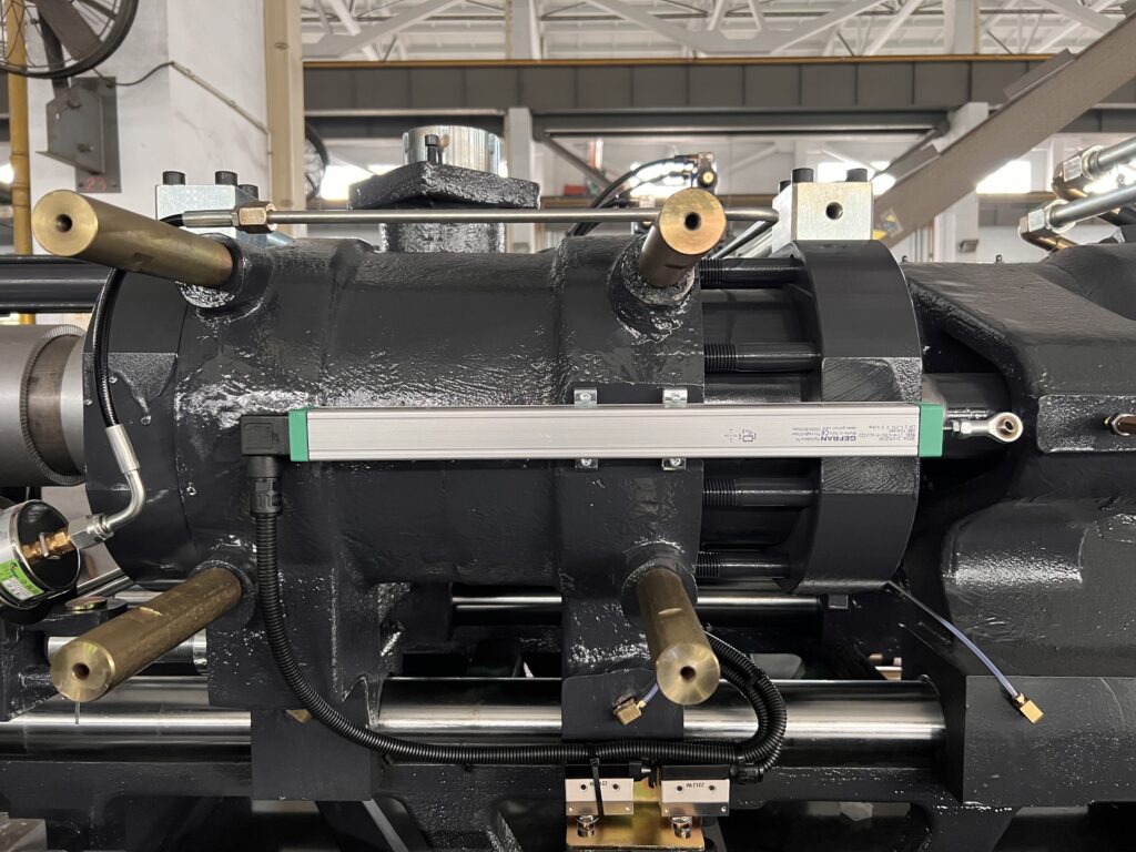
A long linear resistance displacement sensor uses the principle of varying resistance to convert linear displacement into a change in the sensor’s resistance and then into a voltage signal that can be transmitted.
Injection molding machines utilize displacement sensors to detect the linear displacement of the platens and the movement of the screw, and to control their speed of movement and rotation.
Photoelectric switch
An infrared photoelectric switch, also known as a photoelectric sensor or proximity switch, uses an infrared beam to detect the presence or absence of an object.
This is done by measuring the shading or reflection caused by the object on the beam.
The switch uses a synchronous circuit to make this determination.
These types of switches are commonly used in injection molding machines for the safety protection of moving parts, and also for detecting and controlling product drops.
Thermocouple
A thermocouple is a device that measures temperature by using the electrical potential created by two conductors, usually A and B, when they are at different temperatures.
One end of the thermocouple, the working end, is placed in the medium being measured, while the other end, the reference end, is kept at a constant temperature.
When the temperature of the working end changes, the electrical potential also changes, and this information is used to indicate, record or measure the temperature.
Thermocouple is commonly used to control the temperature of the barrel, oil, and mold hot runner in injection molding machines.
The signals are then transmitted to the computer to process and display the temperature value.
Solenoid valve coils
Solenoid valves coils function by passing an electric current through a solenoid coil, which creates a magnetic field.
This magnetic field can be directed in a specific direction and is used to drive various functions of the solenoid valve such as opening or closing it.
Heating coil(bands)
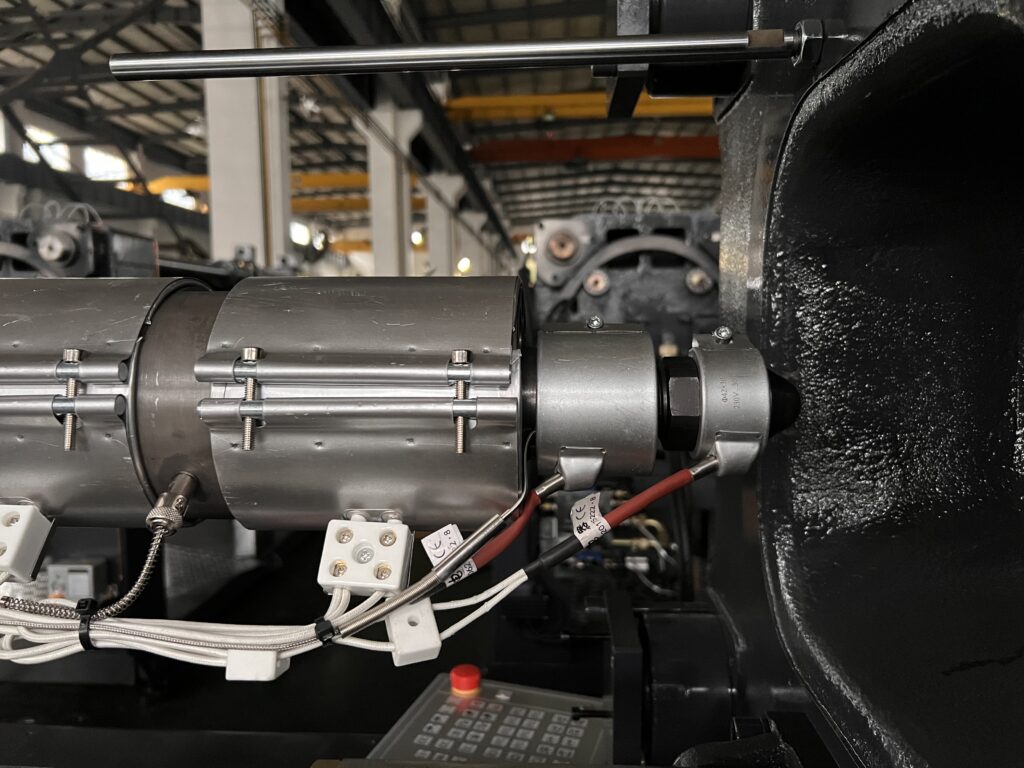
The heating coil is a tool that helps heat the barrel of an injection molding machine.
There are many types of heater in injection moulding machine, but the three most commonly used are mica heater, ceramic heater, and infrared heater.
The infrared heating ring is the most efficient and can save energy, and mica and ceramic heaters are more commonly used.
Servo Motors
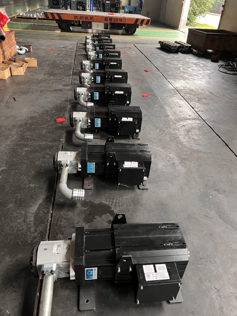
Injection molding machine servo motor uses the appropriate amount of power for each action, resulting in energy savings.
The servo motor is used in all-electric injection molding machines for tasks such as opening and closing the mold, ejecting and demolding, and controlling the injection of raw materials.
It also provides faster and more precise operation, improving production efficiency and the overall production environment.
Additionally, its response speed is much faster than that of a variable pump, at 0.03ms, resulting in a significant improvement in control accuracy.
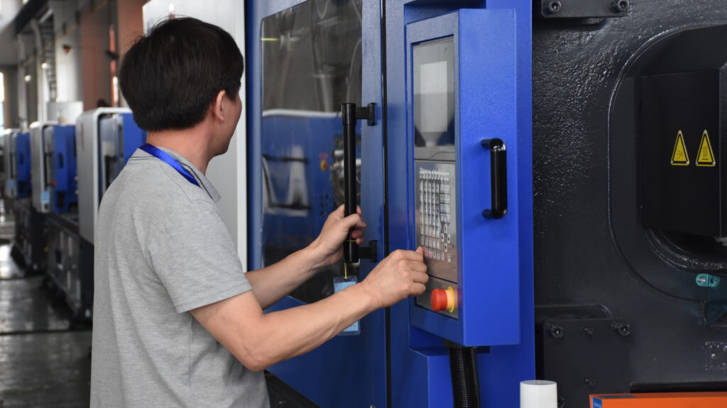
PLC and displays
Injection molding machine PLC
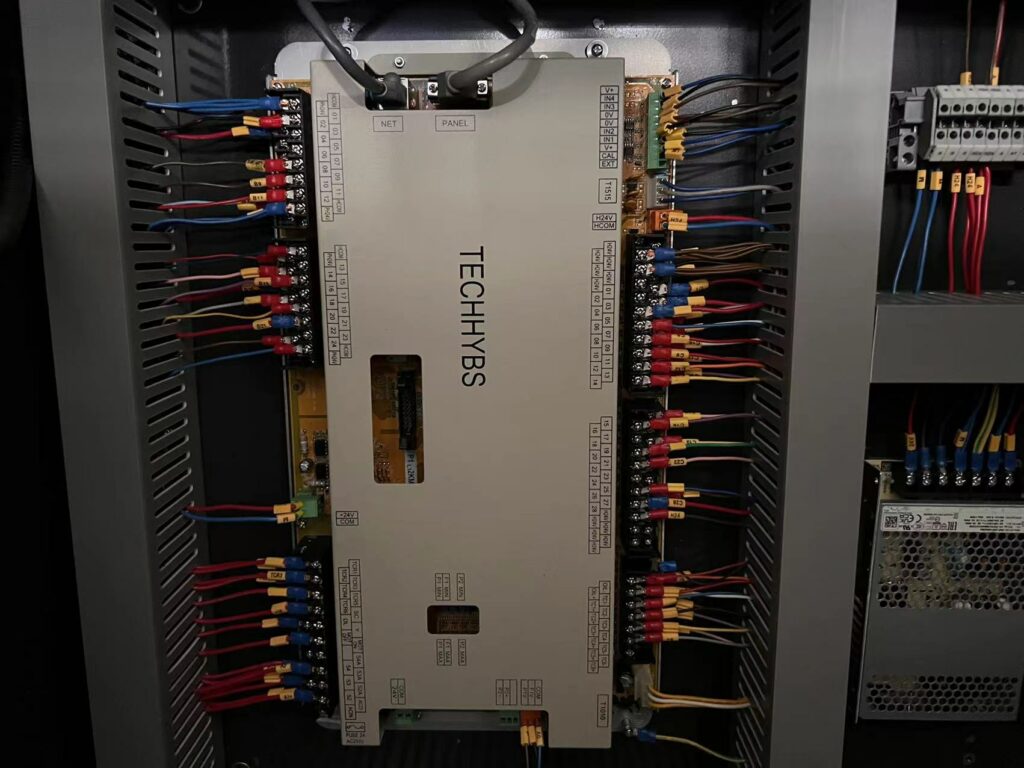
The control system in an injection molding machine uses a controller to manage the various electrical components related to the injection molding process.
The controller is the system that receives and processes operator commands and parameters, reads in sensor data, makes logical decisions, and generates control instructions that are sent to the actuators to control the actions and process parameters of the injection molding machine.
Injection machine displays
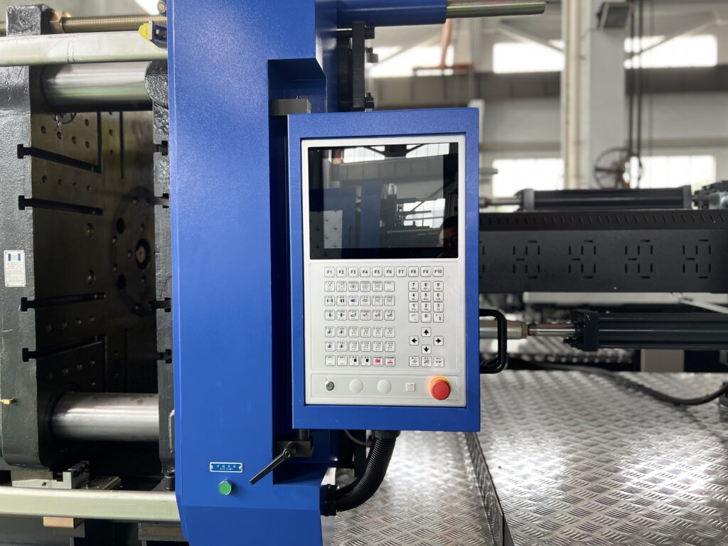
The monitor of an injection molding machine allows for precise control of the injection molding process by displaying and setting various parameters of the machine.
Solid state relays
Solid-state relays (SSR) are non-contact switching devices that are made up of solid-state electronic components.
They work by using the switching properties of semiconductors, such as transistors and thyristors, to turn on and off a circuit without physical contact, which makes them popular in control systems.
These relays can be classified into two types: AC and DC, and are used as load switches for AC and DC power supplies respectively, but they should not be interchanged.
Air switch
An air switch, also known as an automatic air open circuit breaker, is a device that protects electrical equipment by automatically cutting off a faulty circuit when there is an overload, short-circuit, or loss of voltage.
It can also be used to turn on and off a circuit infrequently and control a motor.
Conclusion
In this article, we introduced main parts of injection molding machines, including injection unit, clamping unit, hydraulic unit, and electrical unit. After reading it, you will have a better understanding of injection molding machines.