In this blog, we will study different injection molding nozzle tip types.
The nozzle is a critical component that connects the plasticizing screw and barrel to the mold runner.
The nozzle has a variety of functions:
1.During the pre-moulding process, generating back pressure in the screw head to prevent the melt from the nozzle outflow.
2.During the injection process, generating injection pressure, shear effect, accelerating animation conversion to improve the melt temperature homogenization effect.
3.During holding pressure process, the role of insulation and shrinkage.
Open nozzle tip design
Open nozzle, simple structure, easy to manufacture, small pressure loss, but prone to flow delay.
Figure 1 (a) Figure 1 (b)
Figure 1 (a) shaft hole type, d = 2 to 3 mm, the L = (10 ~ 15) d, suitable for low viscosity, good thermal stability, such as PE, ABS, PS and other thin-walled products.
Figure 1 (b) long cone(full taper), D = (3 ~ 5) d, suitable for high viscosity, poor thermal stability, such as PMMA, PVC and other thick-walled products.
Self-locking nozzle(shut off nozzle) designs
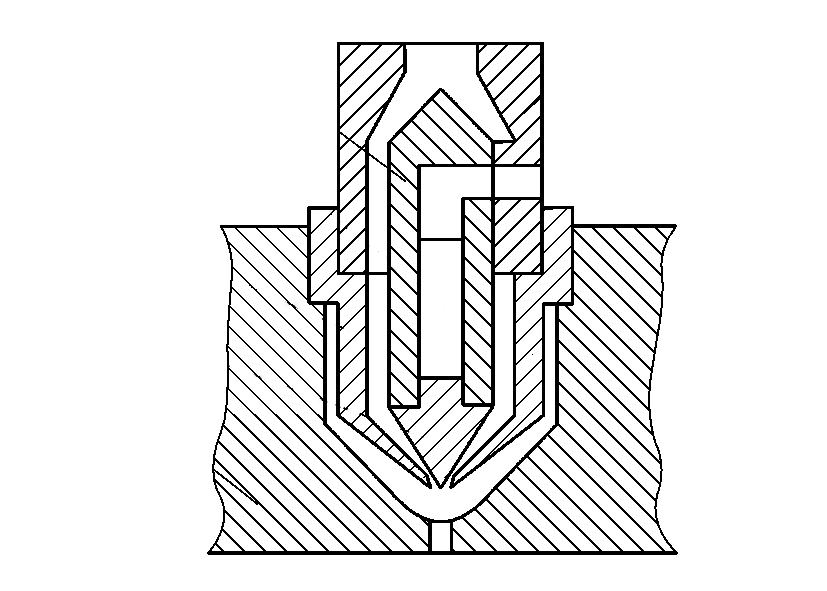
There are various self-locking nozzle structures, as shown in Figure 2.
This structure is mainly used to process certain low-viscosity plastics, such as PA type, to prevent flow delay during pre-molding.
Figure 2 (a) to (f) self-locking principle is the same. In pre-molding, the spring force through the retaining ring and guide rod will be ejector pin pressure, with its cone will be nozzle hole sealed; injection, under the action of high pressure, with the melt pressure in the ejector pin cone formed by the axial force, through the guide rod, gear ring will be spring compression, high-pressure melt from the nozzle hole into the mold runner.
This kind of nozzle causes injection pressure loss, complex structure, cleaning inconvenience, poor anti-flow delay reliability, and easy leak from the mating surface. Figure 2 (g), (h) structure of the action principle is to open or close the nozzle with the help of the injection seat movement force: pre-molding, the nozzle and the main mold sprue disconnected, the melt under the action of back pressure, so that the nozzle core forward closed When injecting, the injection seat moves forward, the main sprue pushes the nozzle core back, the slant hole is opened, and the melt is injected into the mold cavity.
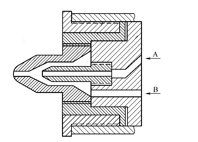
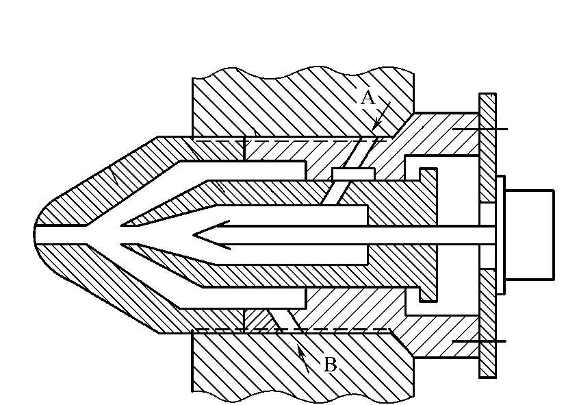
Hydraulic control nozzle
Hydraulic control nozzle structure form, as shown in Figure 3.
An external force manipulates the nozzle ejector pin to seal during pre-molding and open during the injection.
The sealing action of this type of nozzle peg pin participates in the control program of the injection machine, and the nozzle control cylinder needs to be set.
This structure’s seal between the nozzle ejector pin and the guide bush is critical. Under enormous back pressure, there is a possibility of melt leakage, so it is necessary to cooperate with the anti-delay program.
Hot runner nozzle tips
Because the nozzle runner is very thin and in contact with the main sprue of the mold, it is easy to dissipate heat. After holding pressure and cooling, the residual material in the nozzle becomes cold and blocked, affecting the following injection procedure. The cold material also affects the quality of the products. So modern injection molding often uses a hot runner nozzle, and with the hot runner mold, forming a complete set of the hot runner injection system to ensure the quality of products, shorten the injection molding cycle, save raw materials, and reduce energy consumption.
The hot runner nozzle structure form has the adiabatic type and internal heating type.
a. Adiabatic nozzle structure, as shown in Figure 4, is characterized by forming a space between the sprue one and pressure ring three and nozzle 4 to accommodate the material after the first injection is filled with molten material, under the action of a large heat capacity to maintain the temperature of the nozzle flow channel so that it is not blocked, continuous injection.
b. Internal heating type nozzle structure, as shown in Figure 5, its characteristics between the nozzle three and the runner seat 6, fitted with a split fluid 5, which is equipped with Heater, and probe 2; nozzle and mold to form a capacitive material space, to achieve insulation. In injection, the Heater is energized, and the rapid probe heating so that the cold material of the nozzle melts, injection pressure, power off, and the natural nozzle blocking.
Multi-flow nozzle(mixing nozzles)
Multi-flow nozzle with two or more injection molding parts, injection molding mixed color, double or multi-layer composite products, the former is called mixed nozzle, the latter is called composite nozzle.
a. Mixing nozzle structure, as shown in Figure 5.
Outer nozzle 1 and inner nozzle 2 to form the inner and outer flow channel, the outer nozzle through the threaded sleeve 3, 4 and the manifold 5 connected, the inner nozzle directly connected to the manifold, respectively, by the plasticizing device A color and B color melt material in front of the outer nozzle for non-uniform mixing, injected into the cavity to get a variety of decorated mixed-color products.
b. Composite nozzle structure, as shown in Figure 6.
A compound nozzle is with two or more different melt injection devices using the injection process to get specific multi-layer composite products.
The composite nozzle structure features the outer nozzle one and the sliding inner nozzle two and manifold 4 to form the outer flow channel of B material injection, and the internal nozzle two and manifold to create the inner flow channel of A material injection. To make A and B materials form a double-clear color composite product, it is necessary to prevent the two materials from mixing at the nozzle, which is controlled by the ejector needle three, operated by cylinder six according to the process procedure. When the B material is injected, the ejector is manipulated by the cylinder to seal the A material in the inner nozzle; when the A material is injected, the ejector returns the internal nozzle to open, and the outer nozzle shuts the B material in the extreme runner under the action of the A material, so that A and B materials are injected into the cavity respectively according to the procedure, forming a double-clear composite product.
Injection molding nozzle tips set-up
Nozzle tips installation:
The nozzle head and the mold sprue should be concentric, and the two spheres should match closely; otherwise, it will overflow material. Generally, require two spherical spheres of the same radius nominal size, and take the nozzle sphere for the negative tolerance, the diameter of its mouth slightly smaller than the diameter of the sprue 0.5 ~ 1 mm is appropriate, the two coaxial tolerance ≤ 0. 25 ~ 0.3.
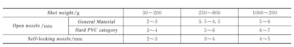
Nozzle tips diameter:
nozzle diameter size is related to the pressure loss, shear heat and the role of shrinkage, materials, injection molding seat and nozzle structure form, as shown in Table 1.
In conclusion, there are many different injection molding nozzle tip types available, each serving a specific purpose and having features to meet the needs of a range of applications. From open nozzles to self-locking, hydraulic control, hot runner, and multi-flow, injection molding nozzle tips can be customized to fit the needs of any project. With the right set-up, these nozzle tips can help ensure a successful injection molding process.